Demo
Circuit
This is the schematics for a PIC USB gamepad that I have built in a steering wheel shell. The code for the firmware was written in PicBasic Pro and it implements a HID USB device with 2 axes and 4 buttons (only 2 buttons connected in the prototype). The device is detected by Windows XP/Vista as a standard USB gamepad and can be used with many games and applications.
I am using a 2 Axes Buffered ±2g Accelerometer from DIMENSION ENGINEERING, it has a built in voltage regulator that allows powering the accelerometer dirrectly from the USB bus (5V):
http://www.dimensionengineering.com/DE-ACCM2G.htm
I highly recommend this accelerometer as well as other great Dimension Engineering products, check out their website: www.dimensionengineering.com !
Note: Optionally you can connect 2 more buttons to RB2 and RB3.
Code
Below is the PIC Basic code that works both on 18F4550 / 18F2550. (There are other requirements to build USB firmware including the HID header, see compiler documentation).
DOWNLOAD HEX FILE FOR PIC 18F2550 (You will need a PIC Programmer to transfer it to the chip, I'm using PICKit2):
IMPORTANT NOTE: Please disconnect any Microchip Devices (including the PICKit2 programmer) before plugging this device since it's using same HID VENDOR /PRODUCT ID provided in Microchip sample files.
If you plug 2 devices with same VENDOR/PRODUCT ID you might get a hardware conflict and the devices might not work.
—————————————————————————————-
Define OSC 48
'CONFIGURATIONS ARE IN /PBP/18F2550.INC , YOU MIGHT WANT TO EDIT THEM
'ADC
DEFINE ADC_BITS 10 ' Set number of bits in result
DEFINE ADC_CLOCK 6 ' Set clock source Fosc/64 => TAD => 1.34uS
DEFINE ADC_SAMPLEUS 50 ' Set sampling time in uS
TRISA.0 = 1
TRISA.1 = 1
ADCON1 = %00001101 ' sets AN0,AN1 to analog mode
ADCON2 = %10101110 '
'bit 0-2: ADCS ,OVERWRITTEN BY ADC_CLOCK, 110: Fosc/64 => TAD => 1.34uS
'bit 3-5: Aquisition time: 101: 12 TAD => 16uS
'bit 6: not used
'bit 7: Right justify for 10-bit
x VAR WORD
y VAR Word
INTCON2.7=0 'RBPU =0 , TURN ON PORTB PULL-UPS
bt1 VAR PORTB.0
TRISB.0 = 1
bt2 VAR PORTB.1
TRISB.1 = 1
bt3 VAR PORTB.2
TRISB.2 = 1
bt4 VAR PORTB.3
TRISB.3 = 1
'USB
buffer Var Byte[3]
USBInit
main:
ADCIN 0,x 'read AN0
ADCIN 1,y 'read AN1
'x,y experimental measurments: ~512 @center / ~365 @ -90deg / -655 @ +90deg
x = (x >> 2) << 2 ' clear last 2 bits
y = (y >> 2) << 2 ' clear last 2 bits
'convert x,y from range [384..512..639] to [0..128..255] with edge clipping
x = ((x MAX 384) MIN 639 ) – 384
y = ((y MAX 384) MIN 639 ) – 384
buffer[0] = y 'gamepad's x-axis is accelerometer's y axis
buffer[1] = x 'gamepad's y-axis is accelerometer's x axis
buffer[2] = PORTB ^ %00001111 & %00001111 'separate and reverse first 4 bits
USBService ' Must service USB regularly
USBOut 1, buffer, 3, main ' Send buffer to endpoint 1
GOTO main ' Do it forever
—————————————————————————————-
Here is how it is detected by Windows XP. Please note that if you don't change the USB HID Vendor ID and Product ID code this device might conflict with other microchip HID devices using same indentification, including the PICKIT II USB programmer (you can't have them plugged in both at the same time).
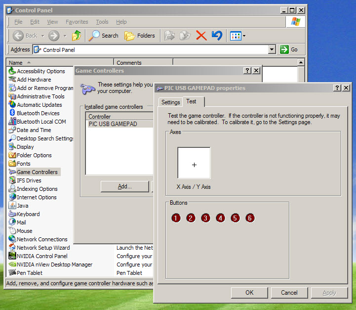
There's no need to calibrate the device on this Windows screen, since it will output values within 0..255 range for both axis and it will be centered close to 128,128 values (we took care of this in the program).
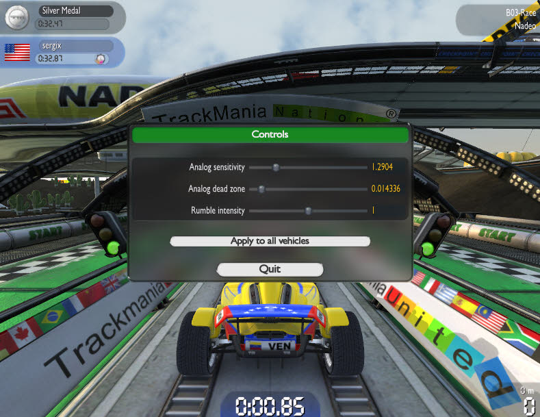
However you might want to adjust sensitivity in your game, based on your preference:
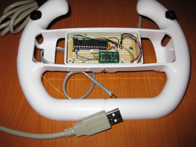
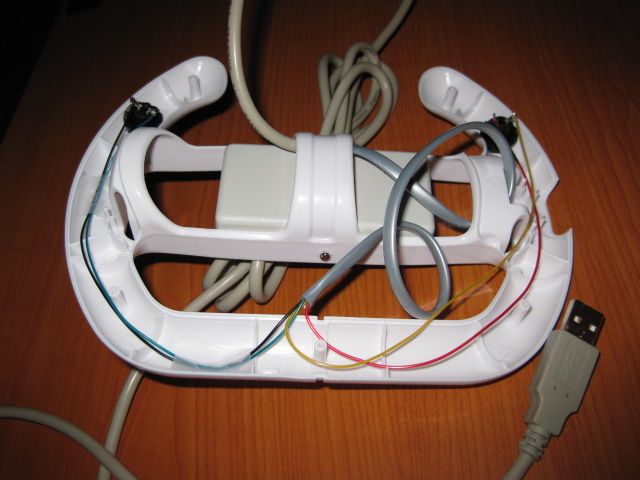
Construction
If using an existing USB cable , the wire coding is VDD red, VSS black , D+ green , D- white.
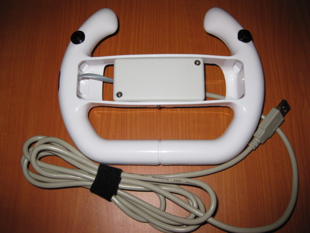
Second prototype using PIC18F2550 chip.in a cheap Wii steering wheel shell. (Look for them on EBay they sell for about $1.45).
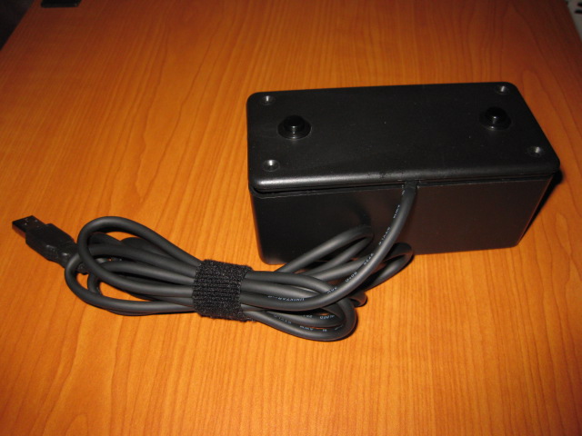
First prototype "THE BRICK" , using PIC18F4550 chip, accelerometer removed.
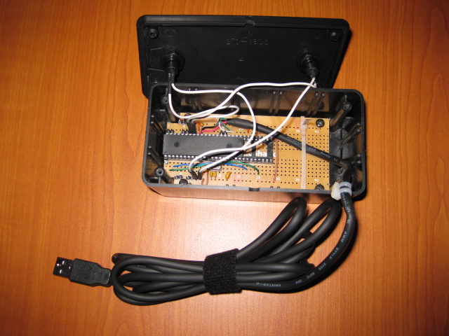
It can work as a motion MOUSE too !
With a slightly different firmware and the same hardware you can build a USB Motion (Tilt/Pan) HID Mouse, source code is here:
http://code.google.com/p/hidmouse/
SVN Trunk:
http://code.google.com/p/hidmouse/source/browse/#svn/trunk/%20hidmouse
Also for anyone interested in a quick build, with all parts and PCB - gamepad kits with pre-programmed PIC and accelerometer are available for 50 USD @ http://gadgetgangster.com/231 .
///starlino///